 Page 2
Page 2
This is how it starts:
Make it yourself comfortable,something to eat,to
drink,bit music you like,the wire-harness diagramm,the soldering Iron,some
shrink-Tubes and a lighter,that's it.
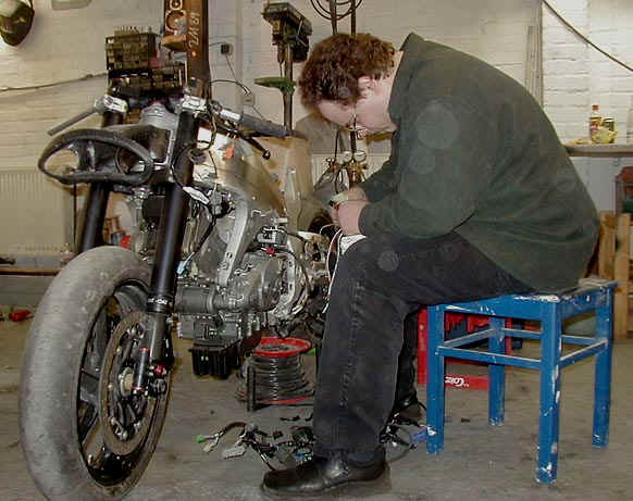
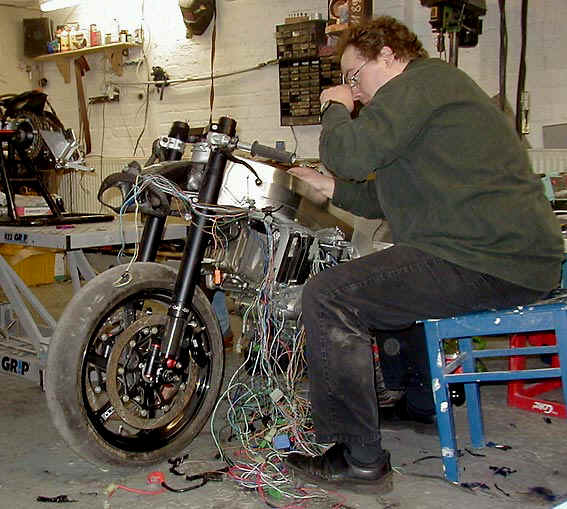
Ok,easy said,it's not me at the 2nd RC,it's Stephen doing this Job-Electronics
is his profession-and we've got a deal,so my Part is: 'i've to develope a custom
adapted cable clutch conversion for his V-Max.So he has got it comfortable,with
something to eat,to drink,but not the music he likes,that's hard,Stephen always
ask ,if I can take out now the cleaning compact-disc.
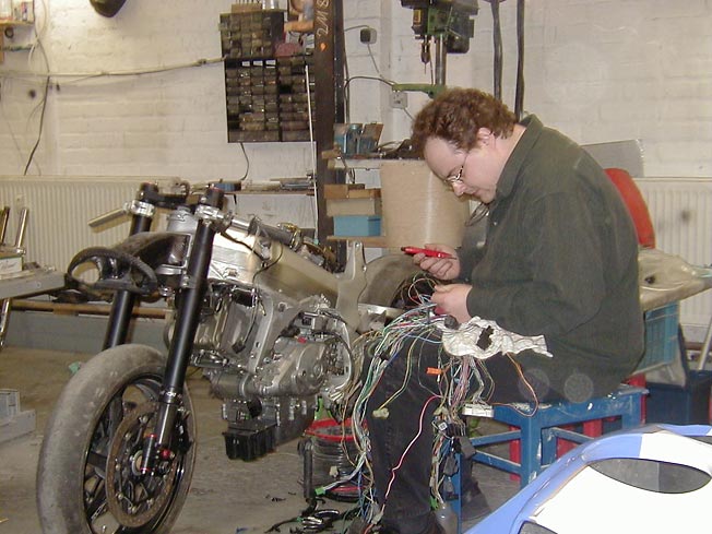
So,take place-use a cutter and free the whole wire harness from the coat,be careful not to hit the wires
The Result you see here,looks terrible,but indeed isn't-you'll agree,when you do your 2nd or 3rd wire harness -mod
So now it's up to you: what do you want ?No recommendations,it's what i do:
-no fuse box (main fuse only)
-no bank angle sensor and no related Fuelcut-Relais
-no high beam-Relais (doesn't mean no high-beam,simply means no relais for it)
-no side stand switch
-no clutch switch
-no std. ignition-switch (will be swapped vs.light Honda MT-8 ignition-Switch)
-no pair-valve
-no flapper underpressure switch
-only one main + and three seperate grounds (i'll explain later)
................here you see some of the Items to get
rid of: 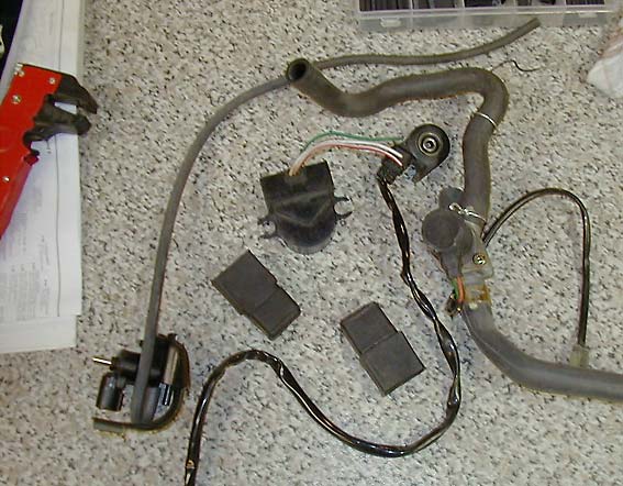
Step 3:fix the main-plug of display where the Plug shall be located in the End(locate also ALL necessary Items,means Fuelpump etc.,where they will be in the end) ,this is one of the main-spots,because nearly 50 % of remaining plugs will end in the garbage can
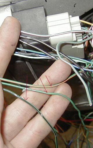
That's what i mentioned above,you've got at least 3 different grounds,here you see green ,green/black and green/orange.In this Pic green/yellow is missing,but-as far as i remenber green/black,green,green/ gray come together ,and at least green /orange and green/yellow are running seperately.Hidden in wire harness coating you've got these connectors,where you can see,what's coming common
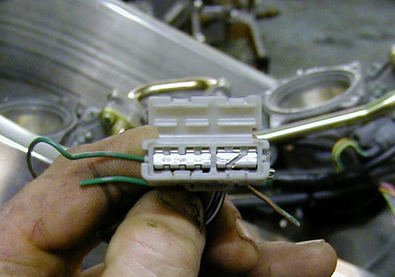 ..........
that's the conector for black/white,green and green /orange-all seperate
..........
that's the conector for black/white,green and green /orange-all seperate
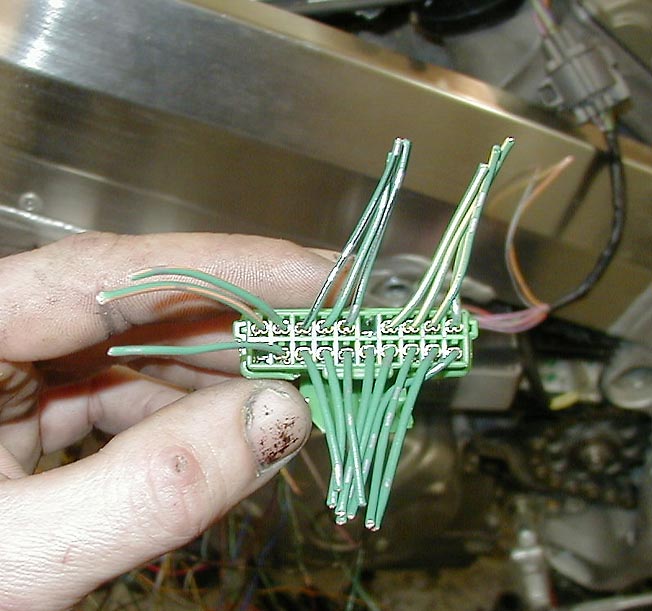 here's the 2nd connector:green/black,green,green/yellow,green orange-all
seperate
here's the 2nd connector:green/black,green,green/yellow,green orange-all
seperate
...........if you remove the cap,you'd see
this :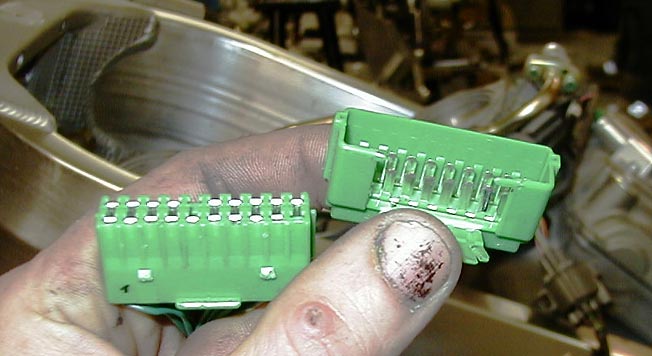
The Explanation for different grounds as Stephen gave me:the CPU runs on TTL-5V-logic,so to avoid errors by the sensors they run on seperate grounds.
The diod-Q now:the diods which regulates
the combination of side stand,neutral and clutch lever switch are located in the
fuse-box-so,if you remove the fuse box:pay attention to connect the
green-green/white (or green -red ?,don't remember yet,i'm at home) at the CPU: 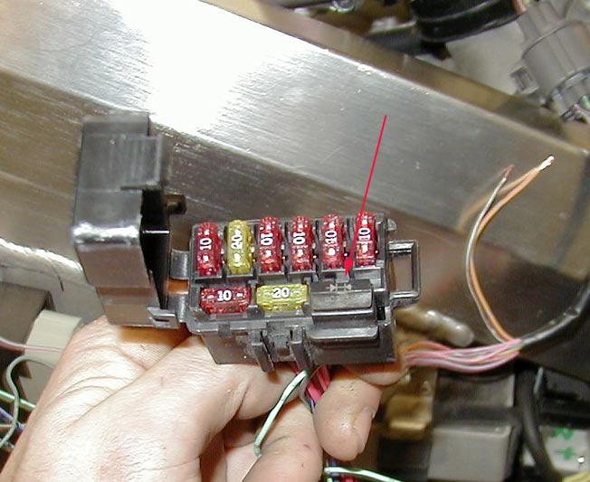
Wellwellwell:if you want to be secure-for support: info@durbahn.de
to be continued...............